Recently I battled to get the Seeed Studio GPRS Shield 1.4 and Arduino Mega 2560 to talk to each other. I eventually discovered that they are not actually compatible when stacked (without some ugly pin jumping, and even then, not really compatible because the Software Serial can’t seem to really handle 19200 baud rates).
So here’s how to treat it as a breakout board. (my notes in blue):
This only requires 5 connections. The blue labels represent the Arduino pins to connect to.
- 5v and GND – These should be pretty obvious.
- Pin 9 – This pin is used to turn the SIM900 on and off.
- Pin 18 and 19 – These are the HW serial pins
Finally note the position of the jumpers (HW Serial) and the position of the Power Switch (Internal).
Which, when connected up should look something like this: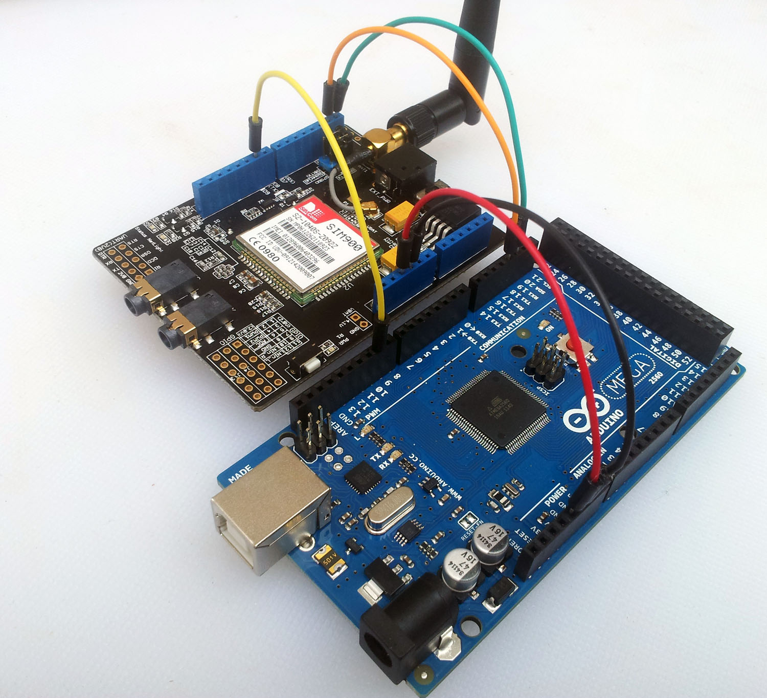
Then finally you can load up the following sketch to get serial access to the GPRS modem via the Arduino’s serial monitor.
#include <SoftwareSerial.h>
#define terminator 10 // DEC value for a LF(line feed) to skip while loop

/*
SETUP

 See https://arbitraryuser.com/2013/04/07/seeed-studio-gprs-shield-and-arduino-mega-2560/

 This code is partially "borrowed" from idS2001 at http://www.seeedstudio.com/forum/viewtopic.php?p=12939#p12939
 */

String IncDataSerial = "";

void setup()
{
  delay(1000);
  Serial.begin(19200);
  Serial1.begin(19200);

  // Automatically power up the SIM900.
  pinMode(9, OUTPUT);
  digitalWrite(9,LOW);
  delay(1000);
  digitalWrite(9,HIGH);
  delay(2500);
  digitalWrite(9,LOW);
  delay(3500);
  // End of SIM900 power up.
}

void loop()
{
  if (Serial1.available()>0)  // if date is comming from softwareserial port ==> data is comming from gprs shield
  {
    boolean getLF = false;
    while(Serial1.available()>0 && !getLF)  // reading data into string if activity is on port and getLF is false ==> no LF have been send
    {
      char buffer=Serial1.read();  // writing data into char
      IncDataSerial += buffer;
      if (buffer == terminator) {
        getLF = true;
      }
    }

    Serial.print(IncDataSerial);  // send string ( char array ) to hardware serial
    Serial.print("\r");   // send a CR because it is missing
    IncDataSerial = "";
  }
  if (Serial.available()>0) // if data is available on hardwareserial port ==> data is comming from PC or notebook
    Serial1.write(Serial.read());  // write it to the GPRS shield
}
In Serial Monitor (or similar app) you will then see it start to talk to you after the initial ~5 second startup delay.
RDY

+CFUN: 1

+CPIN: READY

Call Ready

AT
OK

AT+CSQ
+CSQ:18,0
OK

Hi, why should I use HW serial when I can use SW Serial port 7 and 8 to communicate with the GPRS shield? in this way i haven’t to do that 5 connection that you say
These instructions are specifically for the Mega, where there are issues with SW Serial. Regardless of whether you use HW or SW serial, you’re still going to need to use 5 connections.
why that sim only respond on powerup, but cannot print a reply from the sim900. pls help.
Hi, I follow exactly the same setup, but every time I fire up my Serial Monitor the SIM900 power cut off. The RED LED is off, but the shield power is still on. Any Idea? I am using 12.0V and .5A adaptor for my Mega.
Hi there,
I have also this combination, Arduino Mega and GSM shield You described.
i am agree about issues with SW communication and pin jumping is only way.
Let me ask you about software power up the shield. It just don’t work. I can only power up SIM900 by pressing power switch for 2 sec. Do You know what can it be?
Thanks in advance!!
Hi I have tried wiring my GRPS like you show and I am only gettting ” ÿÿÿÿ” in the serial monitor. It will not send texts (The code from SeeedStudio works to send, dial, etc but will not display in the serial monitor either).
Any suggestions? 🙂
Hi
Thanks for your post.
I have the same hardware as you show. Would you please tell me which library you are using as my board doesn’t respond even though it’s powered up and GSM transmitting.
adding the HW apology can make calls to my gprs
just remove jumpers from serial port selector and wire PIN 10 AND 11 to serial port selector and change SoftwareSerial GPRS(7, 8); to SoftwareSerial GPRS(10, 11) and its work perfectly
could you please provide schematics, i have tried, but still cannot do software power up…
Thanks!
Thank you for posting this I think it will be very useful when my GPRS shield arrives.
I wonder, rather than connecting the 5 leads as a breakout board, can’t you use the board as a shield and just connect a pair of female patch leads to the Rx and Tx pins on the Serial Port select area (in place of the jumpers) and link these to the Mega board pins 18 and 19 which are not obstructed by the GPRS shield?
Hi I have tried wiring my GPS shield like you show. In serial monitor I only gettting ” ”. What should I do?